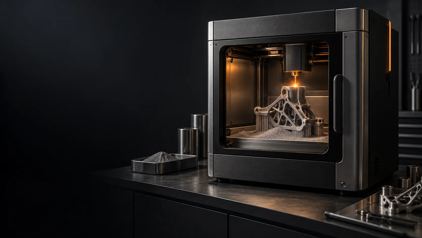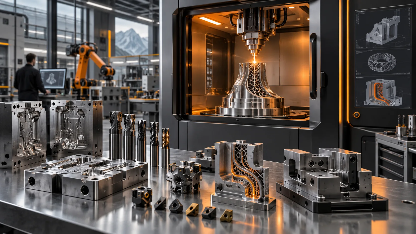
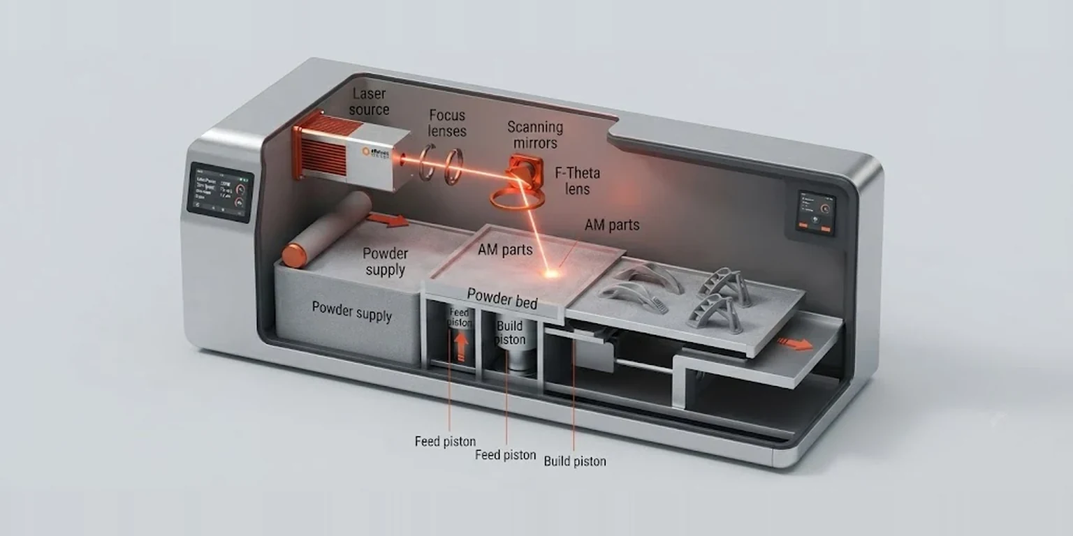
Laser powder bed fusion sounds simple. Spread metal powder, melt the selected areas with a laser, lower the build plate and repeat. Yet a production build may repeat that cycle hundreds or thousands of times before a metal component emerges from the powder bed.
The result depends on far more than the laser. Powder quality, scan parameters, shielding gas, heat flow, part orientation, supports and post-processing all influence the journey from a digital model to an accepted part.
This guide explains LPBF in simple terms for engineers, buyers, students and anyone new to metal 3D printing.
What Is Laser Powder Bed Fusion (LPBF)?
Laser powder bed fusion, usually shortened to LPBF or L-PBF, is a metal additive manufacturing process in which a laser selectively melts regions of a thin metal-powder layer. Another layer is then spread and the cycle repeats until the geometry is complete. NIST describes this as a standard powder bed fusion method.
Unlike machining, which removes material, LPBF adds material layer by layer. That makes internal channels, lattices and complex geometries possible where conventional routes may be difficult or expensive.
LPBF belongs to the powder bed fusion family. Current ISO/ASTM documents use terms such as PBF-LB or PBF-LB/M for laser-based metal powder bed fusion.
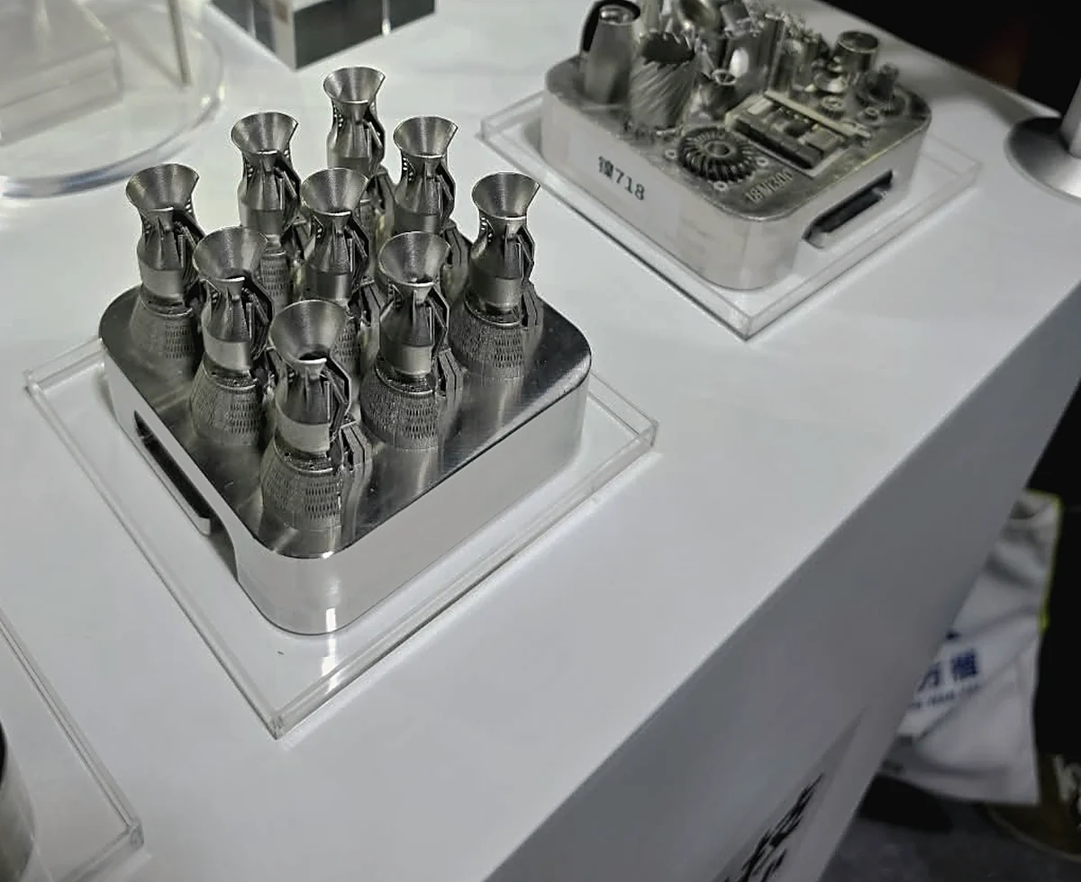
LPBF, SLM and DMLS: What Is the Difference?
These terms often appear together when people compare metal 3D printing technologies. They are closely related, but the terminology is not identical.
| Term | What it means | How a beginner should understand it |
|---|---|---|
| LPBF | Laser Powder Bed Fusion | A widely used generic term for the process in which a laser selectively melts regions of a metal powder bed. |
| PBF-LB/M | Powder Bed Fusion of Metal using a Laser Beam | The formal ISO/ASTM terminology for laser-based powder bed fusion of metals. |
| SLM | Selective Laser Melting | A commercial and historical term for metal laser powder bed fusion. SLM has also been used as a registered trademark by SLM Solutions, now Nikon SLM Solutions. |
| DMLS | Direct Metal Laser Sintering, strongly associated with EOS | Despite sintering in the name, modern EOS DMLS melts the metal powder with the laser. It belongs to the same broader LPBF family as SLM. |
Compare the actual process, supported materials, laser system, build environment and qualification data rather than assuming a different acronym means a fundamentally different method.
How Does LPBF 3D Printing Work?
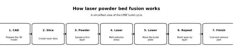
The exact workflow varies by system, but the build cycle can be understood in seven stages.
- Prepare the model and build: the CAD model is checked, oriented and sliced, with supports and scan data added where required.
- Prepare the chamber: the build plate and powder are loaded and the chamber atmosphere is prepared for the material.
- Spread a powder layer: a recoater distributes a thin layer of metal powder across the build area.
- Melt the selected cross-section: the laser scans the areas defined for that layer, melting powder that solidifies and bonds to the material below.
- Lower the build platform by the required layer increment.
- Repeat: a new layer is spread and scanned until the complete part has been built.
- Cool, unpack and clean: the build cools, loose powder is removed and the part moves to post-processing.
LPBF vs Other Metal 3D Printing Methods
Laser powder bed fusion is only one way to 3D print metal. Other processes use metal powder, wire or a liquid binder. The easiest way to understand the difference is to look at how the metal is supplied and how it becomes a solid part.
LPBF vs Directed Energy Deposition (DED)
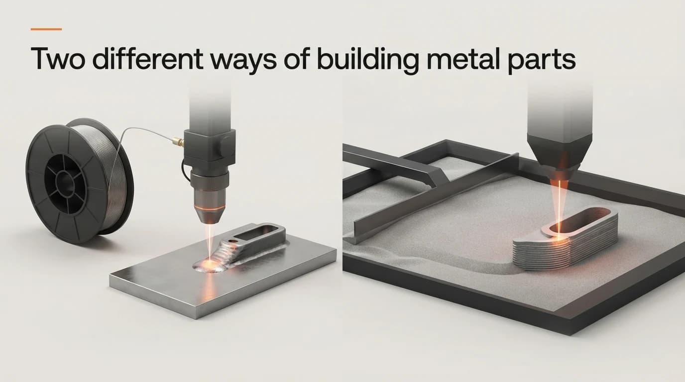
In LPBF, a thin layer of powder is spread across a build plate and the laser melts only the areas needed for that layer. In Directed Energy Deposition, the material is delivered straight to the point where it is needed: powder or wire is fed into a melt pool created by a laser, electron beam or other heat source.
LPBF: material already spread, laser chooses what to melt · DED: machine brings material and heat together at the same place
For a small, complex component with internal channels, LPBF may suit because it builds fine features layer by layer. To add material to a large existing component or repair a worn area, DED is often more practical. Our own comparison of the two feedstocks is in wire vs powder metal 3D printing.
LPBF vs Binder Jetting
Both can start from a bed of metal powder, but they turn that powder into a part in very different ways. LPBF melts the metal during printing. Binder jetting does not normally melt it: a printhead deposits a liquid binder onto selected areas, holding the particles together, and the printed part then needs further processing, typically sintering in a furnace, to become a strong metal component.
LPBF: melt the metal while printing · Binder jetting: bind the powder first, strengthen the part afterwards
LPBF vs Wire-Based Metal 3D Printing
Some systems use wire instead of powder. A common example is Wire Arc Additive Manufacturing, or WAAM, where wire is fed towards the build area and melted with an electric arc, rather like automated welding. Wire-based printing is part of the wider DED family.
LPBF: fine metal powder + laser + powder bed · Wire-based DED: metal wire + concentrated heat + direct deposition
For a relatively small component with detailed features, LPBF is usually the better fit. For a much larger structure where fine detail matters less, a wire-based process can offer a far higher deposition rate.
Which Metal 3D Printing Process Is Better?
No single process suits every application. LPBF works well when a part needs complex geometry, finer features or a high level of design freedom. DED is often more practical for larger components, repair work or adding material to an existing part. Binder jetting prints first and densifies afterwards, while wire-based DED is useful when build size and deposition speed matter more than very fine detail.
In practice the choice comes down to the part itself: its size, shape, material, required finish, production volume and what has to happen after printing.
What Factors Affect LPBF Print Quality?
A good build comes from the interaction of powder, laser energy, heat flow, the chamber environment and the build strategy.
Powder Quality and Powder Spreading
Each layer needs a consistent bed for the laser. Particle shape, size distribution, flow and spreading all affect how evenly the powder settles. An inconsistent layer can carry through into the melt and show up later as reduced density, surface defects or scatter in part quality.
Laser Parameters and Melt-Pool Behaviour
Laser power works together with scan speed, layer thickness, hatch spacing and other parameters. Poorly matched conditions contribute to lack of fusion, pores, keyhole-related voids or cracks. A machine’s maximum laser power is therefore not a simple measure of part quality: process control and validated parameters matter just as much.
Inert Gas and the Build Environment
LPBF systems control the build atmosphere because hot metal can react with gases in ordinary air. Argon is common, while nitrogen suits some materials and machines. Gas flow also helps move process by-products away from the interaction zone.
Heat, Orientation and Supports
Rapid local heating and cooling contribute to residual stress and distortion. Orientation and supports help manage overhangs, heat flow and mechanical stability, but supports add material and removal work.
What Makes a Part Suitable for Laser Powder Bed Fusion?
The better question is not whether LPBF can print a part, but whether it creates a useful manufacturing advantage.
- Complex geometries that would otherwise require multiple conventional operations.
- Internal channels or enclosed flow paths that are difficult to machine.
- Lightweight structures, lattices or topology-optimised designs.
- Part consolidation, where several components can be redesigned as one.
- Low-volume or customised components where dedicated tooling is hard to justify.
- High-value parts where design performance matters more than the lowest possible unit cost.
LPBF is less compelling for large, simple parts that are easy to machine and needed in very high volumes, where another manufacturing route may be more economical.
What Metals Can You Print with LPBF?
LPBF is used with many metal powders, but printability and post-processing needs vary by alloy.
| Material family | Why it is used | Typical application areas |
|---|---|---|
| Stainless steels | Strength and corrosion resistance | Industrial components, tooling, fluid systems |
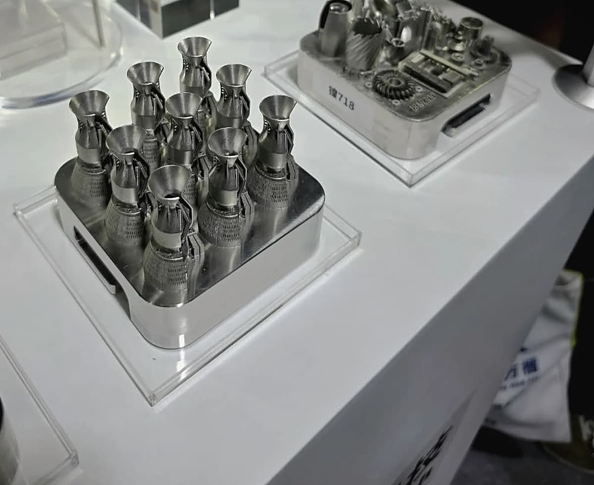
| Titanium alloys | High strength-to-weight ratio and biocompatibility | Aerospace and medical |
| Nickel-based superalloys | Performance at elevated temperatures | Aerospace, energy and demanding industrial parts |
| Aluminium alloys | Low density and lightweight structures | Automotive, aerospace and engineering prototypes |
| Cobalt-chrome | Wear resistance and biocompatibility | Dental and selected medical applications |
| Tool steels | Hardness and wear performance | Tooling, inserts and specialised components |
The range of printable alloys keeps growing, but powder availability does not automatically mean a material is straightforward to qualify for production. See the materials supported across our systems.
Where Is LPBF Used?
- Aerospace: lightweight or consolidated parts and internal flow paths.
- Medical and dental: customised or porous structures.
- Tooling: conformal cooling channels that cannot be drilled in straight lines.
- Research and development: turning complex digital designs into functional metal parts without dedicated tooling.
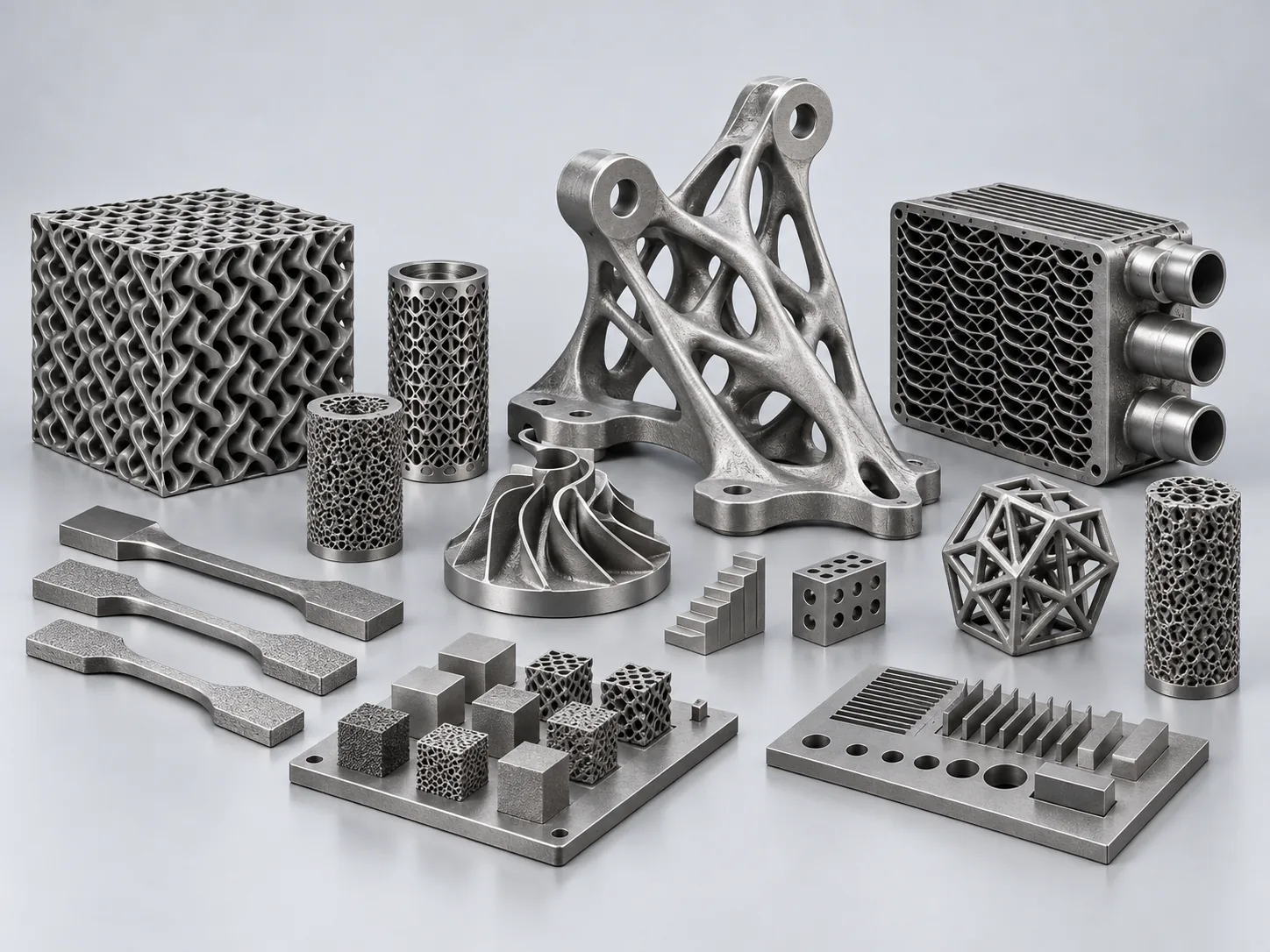
In each case the reason to choose LPBF is the manufacturing advantage created by the geometry, not simply that the part can be 3D printed.
LPBF Advantages and Limitations: Think in Trade-Offs
LPBF is not a universal replacement for conventional manufacturing. Pair each capability with the consequence that has to be managed.
| LPBF can give you... | But you need to consider... |
|---|---|
| High geometric freedom | Design rules, orientation and support requirements |
| Internal channels | Powder removal and access for inspection |
| Part consolidation | Qualification of the redesigned component |
| Lightweight lattices and organic forms | Feature resolution and surface finish |
| Low-volume customisation | Build time, machine utilisation and setup effort |
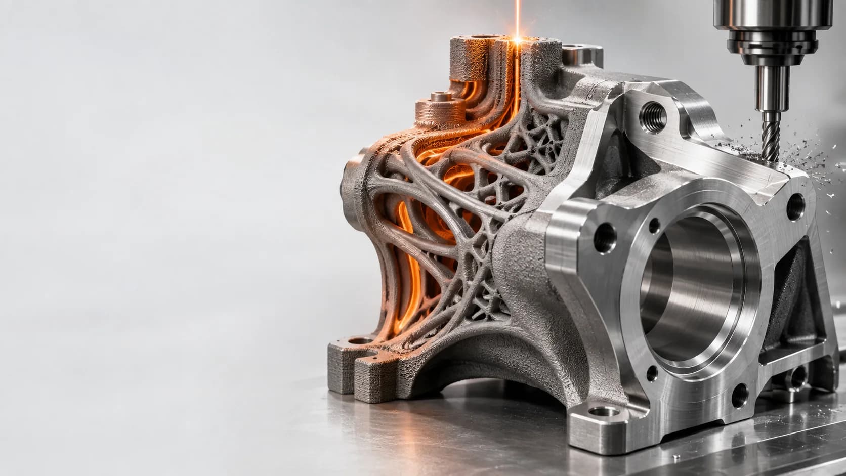
| Near-net-shape metal parts | Post-processing, machining and inspection |
The Print Is Finished. Is the Part Finished?
Usually not yet. Depending on the application, post-processing can include depowdering, build-plate separation, support removal, heat treatment, machining, surface finishing and inspection.
Depowder → Separate from plate → Remove supports → Heat treat → Machine → Finish → Inspect
This matters commercially: difficult support removal or extensive machining can erase some of the advantage created during printing. Not every part requires every stage.
What Affects LPBF Cost and Build Time?
Running cost depends on the machine, alloy, build strategy, labour, finishing and inspection. Focus on the variables that move the cost of an accepted part.
- Part height and the number of powder layers required.
- Laser scan time and the chosen process parameters.
- How efficiently the build plate is filled with useful parts.
- Material price, powder handling and the powder reuse strategy.
- Support volume and ease of support removal.
- Inert gas, consumables, energy and machine utilisation.
- Heat treatment, machining, surface finishing and inspection.
- Failed builds or rework while the process is not yet stable.
Comparing only machine or powder price can be misleading. The more useful figure is the cost of producing an accepted part at the required quality.
Where Is LPBF Heading Next?
Better Monitoring and Defect Detection
More systems use in-situ sensors, imaging and data analysis to spot unusual conditions during a build. The aim is simple: detect problems earlier and make process control more responsive.
More Consistent Powder Beds
Powder-bed monitoring helps identify spreading problems before they continue into later layers, where they become harder or more expensive to correct.
Fewer Supports and a Wider Process Window
Reducing supports saves build space, material and removal work, while better parameter strategies help manufacturers work with more demanding alloys and geometries.
A Practical LPBF Option: Lasefinity’s FusionX
For teams evaluating a compact LPBF system, the FusionX FX-500 lists a 500 W laser, a 100 × 100 × 80 mm build volume and an adjustable 50-200 µm beam. It is aimed at precision manufacturing, research, product development, functional prototyping and end-use metal parts.
Explore the FusionX L-PBF metal 3D printer
As with any LPBF purchase, compare the complete workflow: materials, parameter support, powder handling, atmosphere control, service and post-processing needs. Lasefinity includes installation and operator training with every system.
Is LPBF Right for Your Team?
Before buying a machine or outsourcing a build, start with the application. Define the geometry, material properties, inspection needs, finishing requirements and likely production volume.
For the right part, LPBF turns manufacturing constraints into design opportunities. For the wrong part, it simply adds cost and process steps.
Laser powder bed fusion is a repeated cycle of spreading powder and selectively melting each layer. But powder behaviour, parameters, atmosphere, thermal management, orientation and post-processing all influence the final component. The practical rule for engineers and buyers: evaluate LPBF as a complete manufacturing process, not as a laser specification.
Compare Lasefinity’s metal 3D printing systems