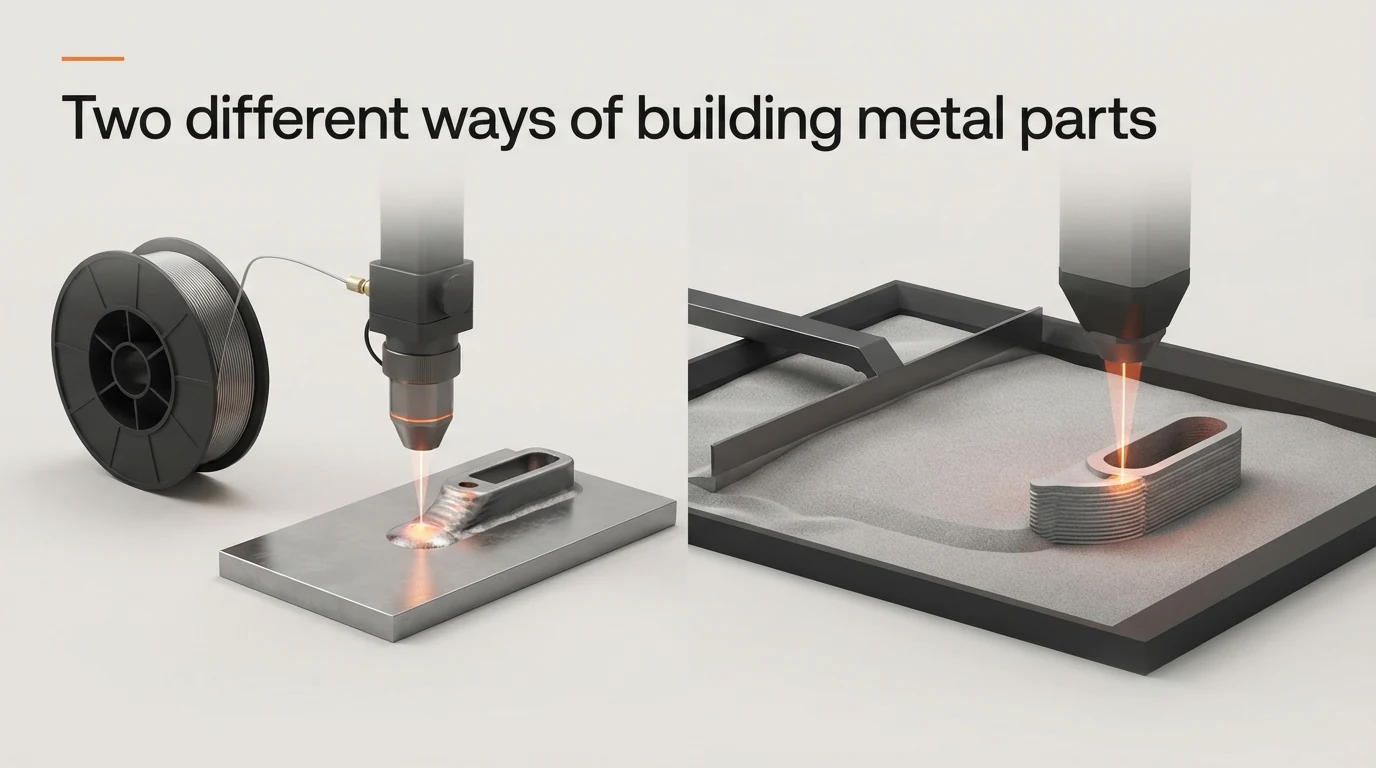
You have a part to make and a budget to work within. But when comparing wire vs powder metal 3D printing, which differences should actually influence your decision?
A printer might offer the detail your design needs yet require more material handling than your team expected. Another might simplify that handling but leave you with additional machining before the part is ready to use. These are the trade-offs that a machine’s purchase price or specification sheet alone cannot fully explain.
For a school, college or laboratory, the question might be how students can gain practical experience within a properly managed workspace. For a small manufacturer, it could be whether a printed bracket will need its mounting faces machined and its holes finished before assembly.
Laser Powder Bed Fusion generally suits fine features and intricate geometries, while laser-based wire printing offers simpler feedstock handling. Choosing between them means understanding how those differences affect your own parts and daily work.
Understanding Wire and Powder Metal 3D Printing
How Powder-Based Printing Works: Laser Powder Bed Fusion
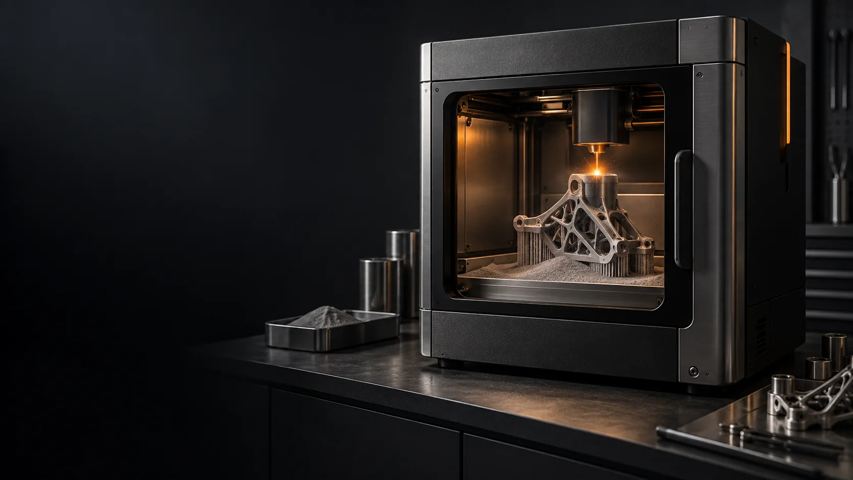
Laser Powder Bed Fusion, or LPBF, builds a component by selectively melting successive layers of metal powder.
A blade or roller called a recoater spreads powder across the build area. A laser scans the required cross-section, melting material that solidifies and bonds to the layer below. The platform lowers, another powder layer is spread and the cycle repeats.
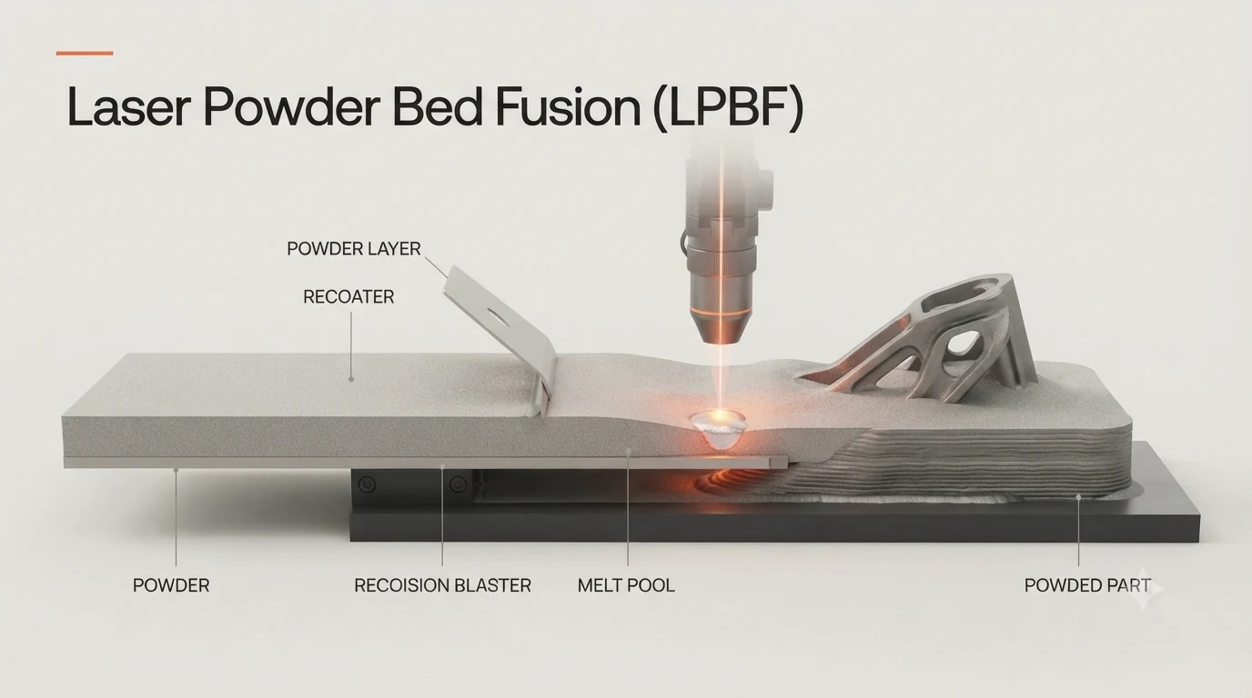
The completed part is surrounded by loose powder, which must be removed. Depending on the geometry, solid supports may also connect the component to the build plate.
NIST’s explanation of powder bed fusion describes this repeated melting and powder-removal sequence.
Metal powder 3D printing also includes other processes. Here, the powder comparison focuses on LPBF because its capabilities and operating requirements differ from powder-fed DED or binder jetting.
How Wire-Based Printing Works: Laser-Based Directed Energy Deposition
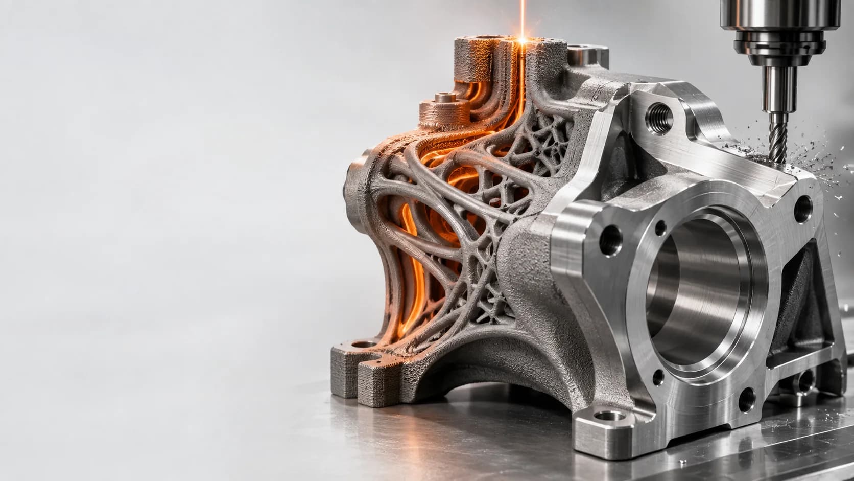
Laser-based wire metal 3D printing feeds solid metal wire into a small region of molten metal called the melt pool. The laser provides heat, and the wire supplies material.
As the deposition head or platform moves, the molten material solidifies into a track. Adjacent tracks and successive layers build the component.
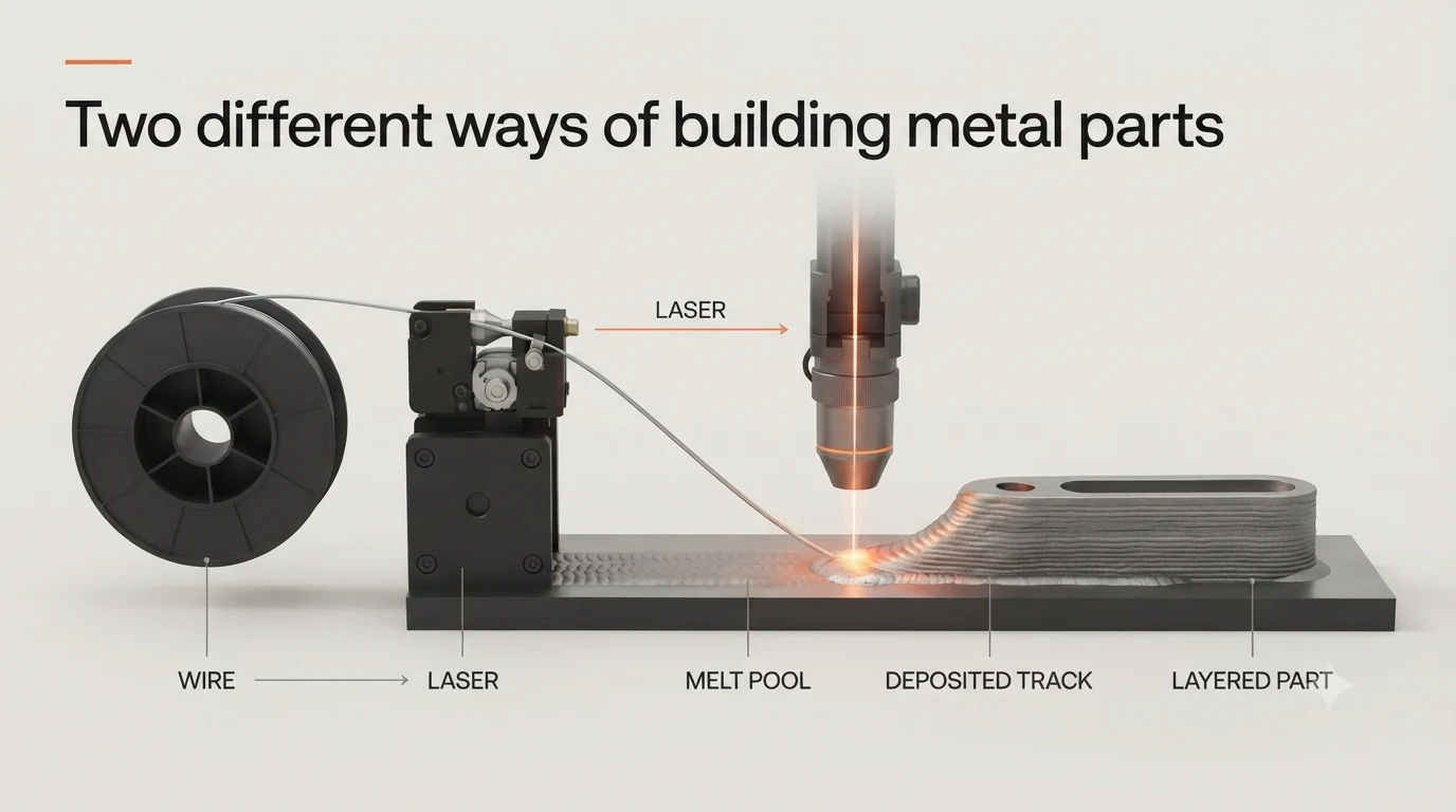
This belongs to Directed Energy Deposition, or DED, which adds and melts material at the point of deposition. NIST describes the underlying DED principle here.
Wire feedstock additive manufacturing can also use an electric arc or electron beam. Those systems have different capabilities, so figures from a large wire-arc installation should not be treated as the expected performance of a desktop laser-wire printer.
Why the Feedstock and Printing Process Matter
The difference is more substantial than replacing a powder container with a wire spool.
LPBF controls where material melts within a spread powder layer. Wire-fed DED must coordinate wire delivery, heat input and movement to maintain a stable deposit.
Consequently, the width of the deposited track, access around the component and heat accumulation all influence the shapes a wire system can produce.
For buyers, the first question should be:
Can this process produce my geometry, including the finishing operations it will need?
Wire vs Powder Metal 3D Printing: Quick Comparison
The table below summarises general tendencies for LPBF and laser-based wire-fed DED. Individual machines, alloys and process settings can change the outcome.
| Factor | Powder-based LPBF | Laser-based wire-fed DED |
|---|---|---|
| Feedstock | Loose metal powder | Solid metal wire |
| Material handling | Requires controlled powder loading, recovery and cleaning | Spools simplify handling and avoid loose feedstock powder |
| Fine features | Generally better suited to thin walls, lattices and intricate geometries | Limited by deposited track dimensions and deposition access |
| Surface finish | Usually finer as printed, but finishing may still be necessary | Often has more pronounced tracks and may require machining |
| Internal features | Can produce complex passages where supports and powder removal are manageable | Enclosed and intricate internal features are more challenging |
| Costs | Includes powder management and associated equipment | Avoids powder-management equipment, but finishing costs still matter |
| Productivity | Depends on layer count, scan strategy and build packing | Depends on deposition rate, toolpath and thermal management |
| Material recovery | Unmelted powder may be reused under controlled procedures | Unused wire stays on the spool; deposited excess may become machining scrap |
| Typical reasons to choose | Fine detail and complex geometry | Simpler feedstock handling, deposition research and suitable near-net-shape parts |
Safety, Handling and Workspace Requirements
Is Metal Powder Dangerous to Work With?
Metal powder can be harmful if breathed in or if it comes into contact with your skin. Some powders can also catch fire or cause an explosion under certain conditions. The risk depends on the type of metal, the size and properties of its particles, how much powder is present and how it is handled.
A sealed printer does not address every exposure point. Loading powder, removing a finished build, filtering recovered material and cleaning equipment also need consideration.
The University of Wisconsin–Madison’s additive manufacturing safety guidance identifies metal-powder hazards and stresses appropriate handling controls. It also warns that conventional vacuum cleaners can create fire or explosion risks when used with metal powders.
Workplace evidence helps explain why the surrounding workflow matters. A German DGUV/IFA investigation covered metal additive manufacturing in 12 enterprises. It found substantial variation in exposure associated with working methods and conditions during preparation and post-processing. The study examined powder-based processes, not a direct wire-versus-powder safety comparison. Read the exposure study.
For a buyer, the implication is practical: ask to see how the whole build is handled, including cleaning, rather than assessing safety only while the machine door is closed.
How Wire Handling and Storage Differ
Solid wire removes the need to pour, sieve and recover loose feedstock powder. That can make material changes and everyday housekeeping easier to manage.
Wire still needs clean, dry storage and identification by alloy and batch. Contamination, surface condition and feeding problems can affect process consistency.
Powder-free feedstock also does not mean emission-free printing. Melting metal can produce fume and particles, and subsequent grinding or machining introduces additional hazards.
For example, loading a stainless-steel spool avoids the powder-transfer task. It does not establish that the deposition process can operate without an appropriate extraction assessment.
Ventilation, Protective Equipment and Operator Training
Safe metal 3D printing requires controls matched to the machine, material and tasks being performed.
Both routes need consideration of laser containment, hot surfaces, moving equipment and shielding gas. Released inert gas can displace oxygen, so room conditions and gas arrangements matter. The university guidance also identifies these hazards and the importance of manufacturer instructions and functioning interlocks.
Where metal working produces fume, extraction should capture it effectively. HSE’s guidance on controlling welding fume explains the role of local exhaust ventilation, suitable respiratory protection where needed and maintained controls. The exact arrangements for a printer require assessment of its process and installation.
For schools and laboratories, request a task-based demonstration covering loading, printing, unloading, cleaning and maintenance. Establish which activities trained staff will perform and which students may undertake under supervision.
Purchase Price and Running Costs
Upfront Machine and Installation Costs
Neither feedstock gives a reliable shortcut to the total purchase cost.
Compare quotations for an operational installation, including cooling, gas supply, extraction, software, commissioning and training. For LPBF, also establish what powder-handling and recovery equipment is included.
The machine’s footprint is only part of the space requirement. A compact printer may still need room for servicing, a chiller, material storage and finishing equipment.
A useful question is: what must be purchased or installed before the first representative part can be completed?
Wire vs Powder Feedstock Costs
Commercial wire can offer a feedstock cost advantage for some alloys, but there is no universal price ratio.
A meaningful comparison uses the same alloy grade, relevant quality requirements, order quantity and supplier terms. A commonly available welding wire and a tightly specified additive-manufacturing powder are not automatically equivalent purchasing propositions.
For powder, ask about particle-size requirements, minimum quantities and reuse procedures. For wire, check diameter, surface condition, spool compatibility and the availability of validated printing settings. See the materials supported by each Lasefinity system.
Price per kilogram is useful only when combined with how much material the finished part requires.
Gas, Electricity, Maintenance and Consumables
Running costs extend beyond the feedstock.
LPBF cost estimates should consider recoater wear, filtration, powder recovery, build plates and cleaning. Wire-system estimates should consider feed components, guides, deposition hardware, optics and cooling. Both may incur gas, servicing, software and inspection costs.
Laser power is not the same as electricity consumption. A laser’s optical output does not represent the total electrical demand of its cooling equipment, motion system and other components.
Ask for expected consumption over a representative build cycle rather than estimating costs from the laser wattage alone.
Why Cost Per Finished Part Matters
A useful comparison is:
Cost per accepted part = Total allocated production cost ÷ Number of parts that meet the requirements
Include machine time, labour, consumed material, finishing, inspection and rejected builds.
Consider an illustrative bracket that needs two flat mounting faces and accurately positioned holes. If the wire-printed version requires machining all three features, those operations belong in its quotation. The LPBF version may also need finishing, but the amount could differ.
The cheaper feedstock does not necessarily produce the cheaper accepted bracket. When comparing wire vs powder metal 3D printing, ask suppliers to quote for the same part, including the machining and inspection needed before it can be used.
Detail, Accuracy and Surface Finish
Fine Features, Thin Walls and Complex Shapes
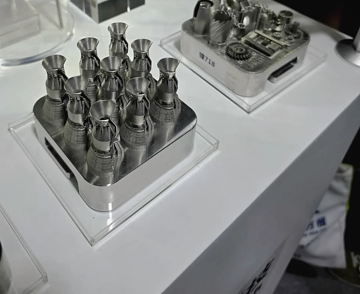
For parts with small features and intricate structures, metal powder 3D printing using LPBF generally has an advantage over laser-wire DED. A wire-fed system builds with deposited tracks, which limit how small or closely spaced its features can be.
Picture two proposed teaching parts: an open lattice with many slender struts and a simple wall built to study deposition behaviour. They test different capabilities. The lattice emphasises geometric detail; the wall makes track formation and heat effects easier to examine.
A specification can help, but it needs interpretation. Lasefinity lists an adjustable 50–200 μm beam size for FusionX. That describes the laser beam, not a guaranteed minimum wall thickness or dimensional tolerance.
Explore the FusionX LPBF system
Similarly, a wire diameter does not directly establish the width of the resulting track. Heat input, travel speed and feed rate influence how the material spreads.
Dimensional Accuracy and Repeatability
Three different questions are often compressed into the word “precision”:
- Feature capability: can the machine form the shape?
- Accuracy: how close is the result to the intended dimensions?
- Repeatability: how consistently can it achieve that result?
Layer thickness does not answer all three.
For scale, NIST documents a powder-spreading experiment using a 40 μm layer height, equivalent to 0.04 mm. At that height, a 20 mm vertical build would contain 500 layers. This is an illustrative calculation using the experiment’s setting, not a specification for every LPBF machine.
Thin layers alone cannot guarantee accurate holes or flat surfaces. Thermal distortion, orientation, calibration and subsequent processing also affect the result.
Ask suppliers for measured samples in the intended alloy, with clear identification of which surfaces were machined.
Surface Finish and Post-Processing
Both processes can require work after printing.
LPBF surfaces can retain texture from particles, layer steps and support contact. Wire-fed surfaces often show more visible deposition tracks. Depending on the application, machining, grinding, blasting or polishing may be required.
Accessibility is crucial. An external face may be straightforward to machine. An internal passage may be difficult to inspect or finish.
For an LPBF cooling channel, the design must also allow trapped powder to escape. A passage that looks acceptable in CAD still needs a workable removal and verification procedure.
This makes post-processing part of the design decision, not something to resolve after buying the machine.
Materials, Build Volume and Part Size
Which Metals Can Each System Process?
Material compatibility should be checked at alloy and process level.
A listing for “stainless steel” is a starting point. Buyers should establish the grade, available parameter sets, feedstock requirements and evidence for the properties they need.
For a research project, the ability to develop new parameters may be valuable. For routine production, a validated starting process and documented results may matter more.
Also distinguish a successfully printed shape from a qualified component. Strength, fatigue performance and other required properties may depend on build direction, defects, heat treatment and inspection.
A sensible supplier discussion starts with the intended service conditions: what load, temperature, environment and dimensional requirements must the part withstand?
Build Volume and Practical Part-Size Limits
Build volume tells you how much space a printer has to build a part. However, your component may need extra room for supports, fixtures that hold it in place, or the angle at which it is printed.
To see what this means in practice, consider Lasefinity’s two metal 3D printing systems:
| Specification | FusionX | WireX |
|---|---|---|
| Process | LPBF | Laser-based wire-fed DED |
| Build volume | 100 × 100 × 80 mm | 150 × 150 × 170 mm |
| Laser power | 500 W | 900 W |
| Feedstock-related specification | Adjustable beam size: 50–200 μm | Wire diameter: 0.4–0.8 mm |
WireX offers a larger build space in this comparison. These dimensions apply to these two machines, though. They do not mean that every wire-based printer can make larger parts than a powder-based system.
For example, a part measuring 95 mm across might appear to fit within a 100 mm build space. But if it needs supports extending outwards or must be tilted for printing, it could require more room.
Before choosing a machine, share your CAD model with the supplier and ask them to check how the part will fit, including any supports or fixtures it needs.
Matching the Process to the Part
A useful evaluation model should contain the features that make your work difficult: perhaps a thin wall, a mounting hole, an overhang or a sealing surface.
A simple demonstration cube can show that material was deposited. It cannot establish whether the machine will produce your component successfully.
Request the printed sample, its measured results and the complete finishing sequence together.
Speed, Productivity and Material Waste
Printing Speed Versus Total Production Time
Different speed figures describe different things.
Laser scan speed measures beam movement. Wire feed speed measures material entering the process. Deposition rate measures material added over time. None is automatically equivalent to finished parts per day.
LPBF productivity depends on scanning, recoating, layer count and the arrangement of parts within the build. Wire deposition depends on track formation, movement, starts and stops, and thermal management.
A wire process that deposits material quickly may still need pauses to manage heat and additional machining afterwards. An LPBF build can distribute preparation time across several components, but each component still adds scanning work.
Compare the elapsed time from build preparation to inspected parts, including cooling, removal and finishing.
Material Use, Recovery and Reuse
In metal powder 3D printing using LPBF, powder that has not melted during the build is not automatically waste.
However, recovered powder should not be assumed equivalent to fresh powder indefinitely. Its condition and contamination history matter. Filtering removes certain unwanted particles; it does not by itself verify every relevant material property.
Unused wire remains on the spool, making the feedstock balance easier to follow. Yet material deposited outside the final geometry may later become machining chips.
This creates an important distinction between material entering the deposit and material remaining in the finished component.
How Finishing and Failed Builds Affect Productivity
Consider a hypothetical wire deposit weighing 1 kg that becomes a 700 g finished part after machining. In that example, 30% of the deposited mass is removed, even if very little wire was lost during deposition.
That is an illustrative material balance, not a reported performance figure for WireX.
The same accounting should include LPBF supports, rejected powder and failed builds. Recyclable scrap can have value, but producing and processing it still uses resources.
Ask for a material balance and production-time estimate for your sample part. These are more informative than a general claim of “minimal waste”.
Which Method Should You Choose?
For Schools and Technical Training
Wire metal 3D printing is worth considering for lessons on how metal is deposited, especially where simpler material handling would help staff and students.
For example, a course exploring how movement and heat input affect a deposited wall may benefit from a wire-fed platform. A course centred on lattice design and powder-bed processing may need LPBF.
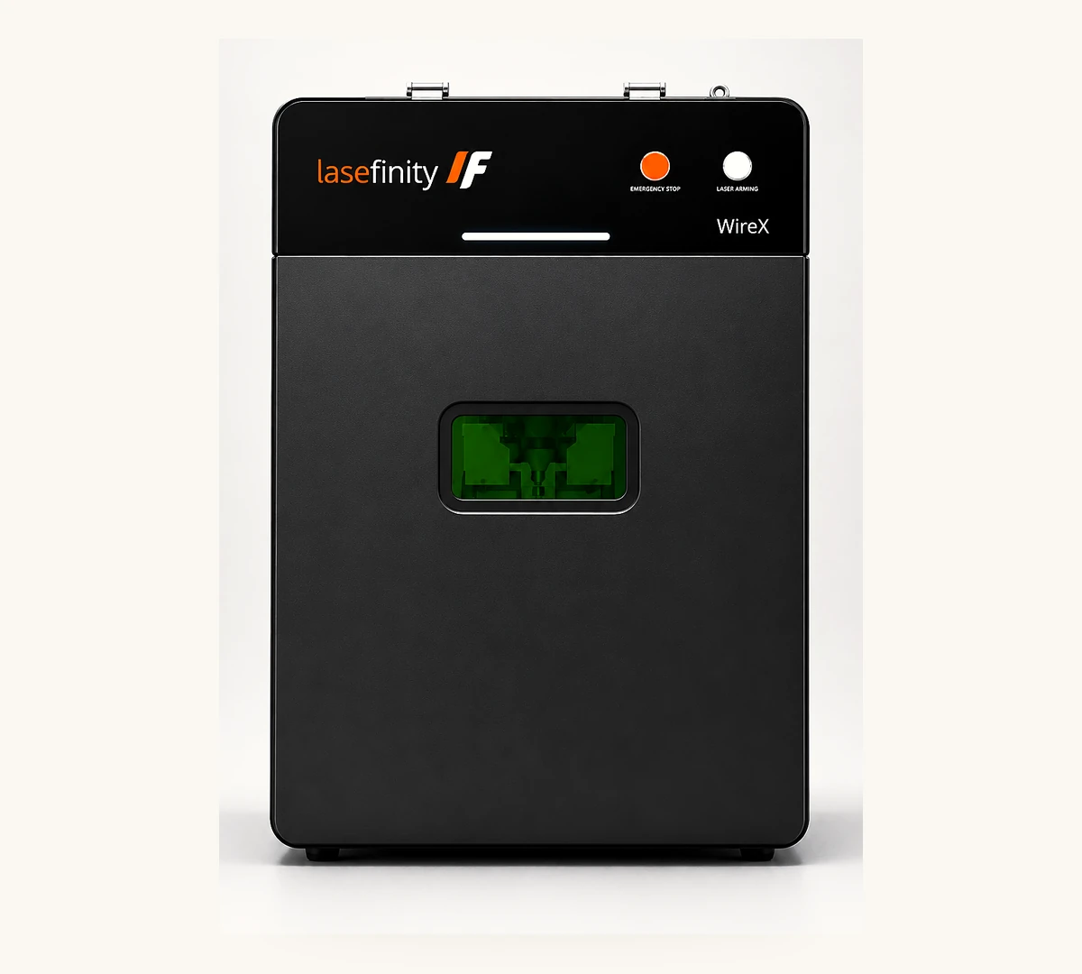
Lasefinity’s WireX is positioned for research, education and prototyping. Its catalogue lists a 150 × 150 × 170 mm build volume, 0.4–0.8 mm wire compatibility and melt-pool monitoring. These provide concrete points to assess against proposed teaching exercises.
Explore the WireX desktop metal 3D printer
For safe metal 3D printing in a teaching environment, check the installation requirements and agree who will load materials, remove parts and clean the equipment. Students need training and supervision for the tasks they undertake. Lasefinity includes installation and operator training with every system.
For Research and Prototyping
Choose according to the question the research needs to answer.
Fine geometric structures may favour LPBF. Studies of wire delivery, deposition behaviour or adding material to an accessible surface may favour wire-fed DED.
For functional prototypes, identify what is being tested. A prototype for checking assembly fit has different requirements from one used to evaluate fatigue behaviour.
Lasefinity’s FusionX provides an LPBF option with a 100 × 100 × 80 mm build volume and a 500 W laser. Researchers considering it should review material support and process-control requirements alongside geometric needs.
For Small-Batch Production
Evaluate both options against the same part drawing and acceptance criteria.
Request evidence for:
- The required alloy and material condition.
- Critical dimensions and surface finish.
- Total labour, printing and finishing time.
- Inspection requirements and repeat-build consistency.
- Cost per accepted part at the intended batch size.
LPBF may justify its powder workflow where geometry creates value. Wire-fed DED may be attractive where the shape is suitable for deposition and the finishing route is straightforward.
Neither “powder” nor “wire” is a purchasing specification on its own.
Choosing a System Around Your Actual Work
The choice between wire vs powder metal 3D printing comes down to your parts and the work needed to finish them. Can the system produce the required features, and can your team manage the handling, finishing and inspection within your budget?
Start with geometry, material and acceptance requirements. Then assess handling, facilities, finishing, productivity and total cost.
When discussing FusionX or WireX with Lasefinity, share a representative CAD model and explain how the finished component will be used. That gives the comparison a concrete basis and helps identify the process, configuration and supporting equipment your work requires.
Compare Lasefinity’s metal 3D printing systems