Design for additive manufacturing (DfAM) is an engineering approach to designing metal parts around the capabilities and limitations of a specific 3D printing process. A component may look perfect in CAD but become difficult to manufacture because of unsupported overhangs, thin walls, trapped powder or thermal distortion. These issues are far easier to address during design than after an unsuccessful build.
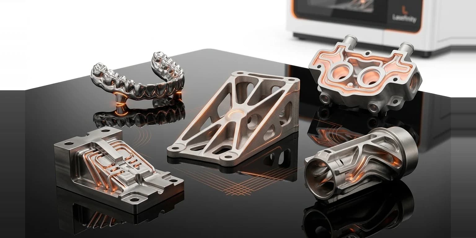
Metal 3D printing offers greater geometric freedom than many conventional manufacturing methods. Engineers can develop internal cooling channels, lightweight structures and intricate parts that might otherwise require several machining or assembly operations. That freedom comes with process-specific limitations: successful design has to account for supports, build orientation, heat flow, material behaviour, cleaning and post-processing from the beginning.
This guide explains the core design rules for metal 3D printing, with practical examples from Laser Powder Bed Fusion (L-PBF) and wire-fed Directed Energy Deposition (DED). It also shows how good design can improve performance, reduce avoidable manufacturing costs and prevent common build problems.
What Is Design for Additive Manufacturing (DfAM)?
DfAM is an engineering approach that considers a manufacturing process’s capabilities and limitations while the component is being designed. Instead of developing the geometry first and solving production problems later, DfAM brings functional, manufacturing and inspection decisions together from the start.
Traditional manufacturing creates different constraints: machining requires cutting-tool access, while casting may require draft angles and mould separation. Metal additive manufacturing changes some of those requirements. L-PBF can produce a curved cooling passage that would be difficult to drill conventionally — yet the passage still needs enough clearance for powder removal and must meet its flow and inspection requirements.
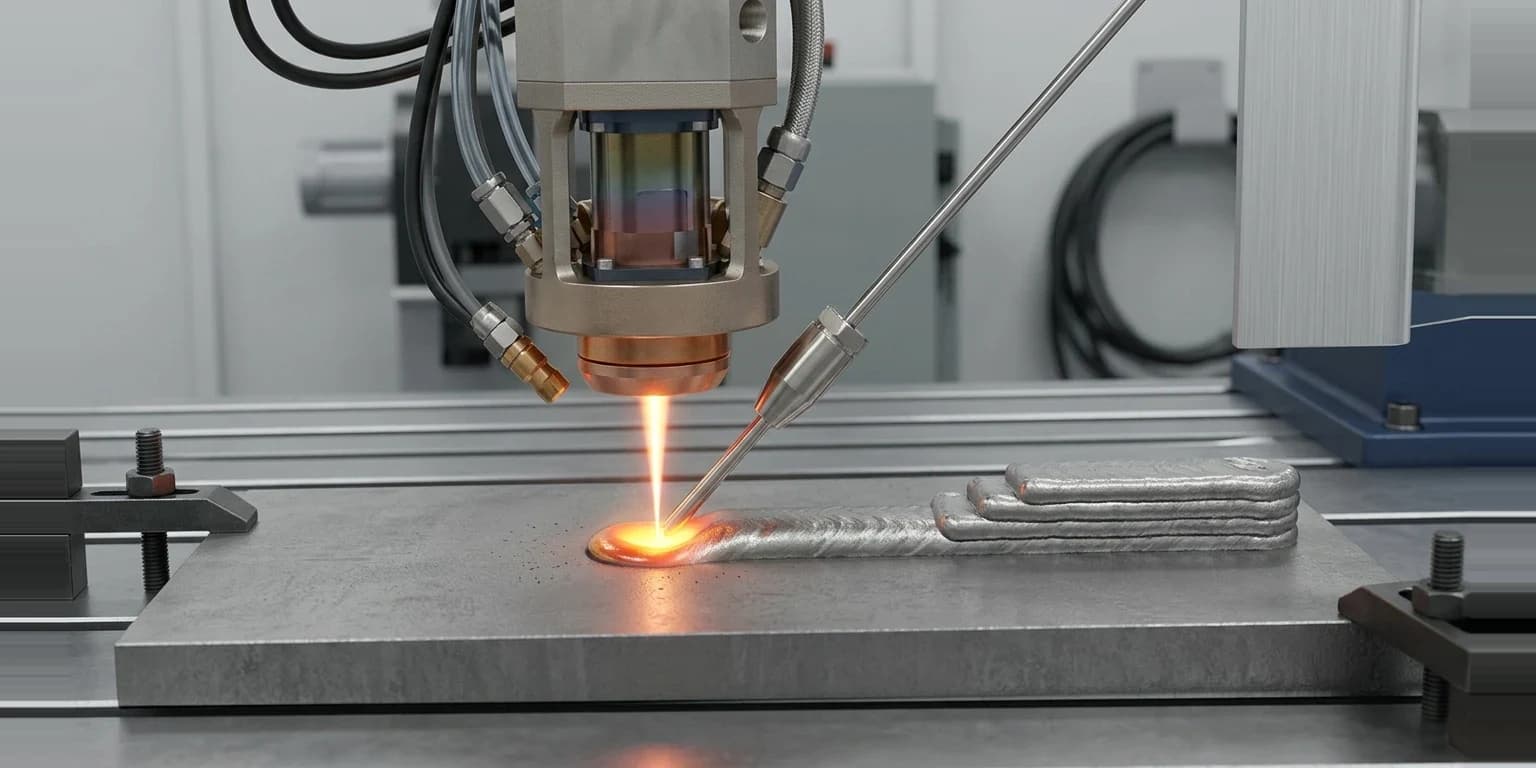
Wire-fed DED raises different questions, because material is deposited along a programmed path. A part may be geometrically plausible but unsuitable if the deposition head cannot access the intended region. Good DfAM answers three questions together: can the part be manufactured, will it perform as required, and can it be finished and verified? A design that satisfies only the first question is not production-ready.
Selecting the Right Metal Additive Manufacturing Process
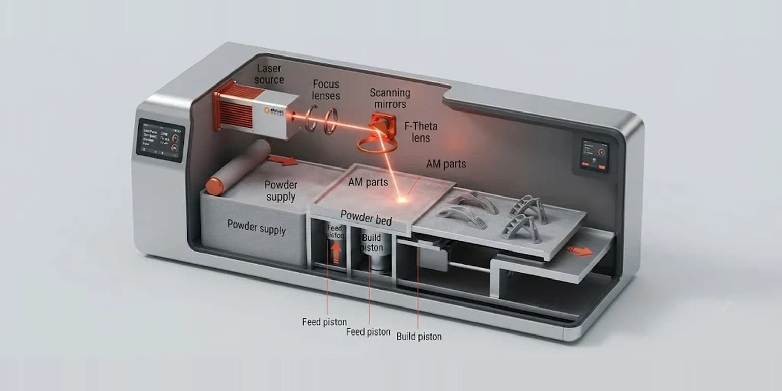
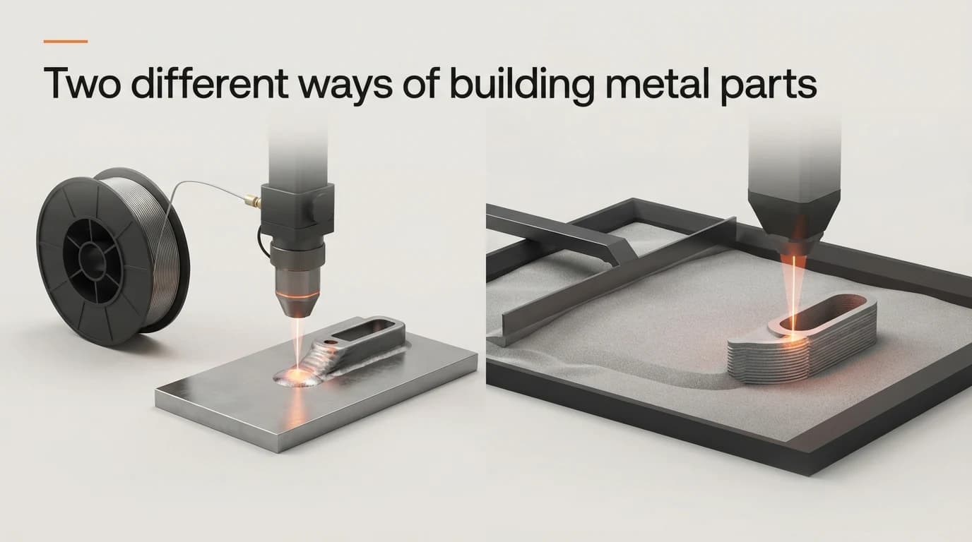
Process selection should come before detailed design rules, because not every metal AM technology has the same constraints. L-PBF selectively melts regions of metal powder across successive layers, which suits relatively fine features, intricate geometry and complex internal passages where powder removal is possible. Wire-fed DED melts and deposits metal wire along programmed paths, which suits controlled material addition, suitable repairs, cladding and near-net-shape structures.
A near-net-shape component is manufactured close to its final geometry but may still need machining to reach specified dimensions or surface finish. The right choice depends on part dimensions, access, feature resolution, materials, required properties and finishing operations — not on which process is more fashionable.
L-PBF vs Wire-Fed DED: Key Design Differences
| Design consideration | L-PBF | Wire-fed DED |
|---|---|---|
| Fine features | Generally suits finer detail and more intricate geometry | Limited by deposited bead dimensions and stability |
| Overhangs | May require supports or a different build orientation | Depends on deposition strategy, bead stability and head access |
| Internal channels | Complex passages are possible; powder removal is essential | Fine enclosed channels are generally impractical |
| Orientation | Influences supports, heat flow, surface finish and build time | Influences access, heat flow and bead formation |
| Finishing | Support removal, heat treatment and machining may be needed | Machining is commonly planned for critical surfaces |
| Repairs | Not usually preferred for direct deposition onto existing parts | Can add material to accessible regions of existing components |
These are broad process characteristics rather than guaranteed capabilities of any particular system. For the differences in feedstock, feature size and operating requirements, see our guide to wire vs powder metal 3D printing.
Why DfAM Matters for Metal Parts
Lower cost and fewer failed builds
Metal AM costs go well beyond machine time and powder or wire. They also include build preparation, support removal, heat treatment, machining, cleaning and inspection. A bracket with a large horizontal overhang might need substantial supports in its initial orientation; rotating it or modifying the geometry could cut those supports and shorten finishing, provided the revised design still meets its functional requirements.
Failures have costs too. A part with inaccessible powder, unsupported geometry or excessive distortion may be unusable even when the print completes. DfAM brings those risks into the design review instead of discovering them after a full build. The objective is not simply a lighter or faster print, but a lower cost per accepted component.
Better strength and lighter weight
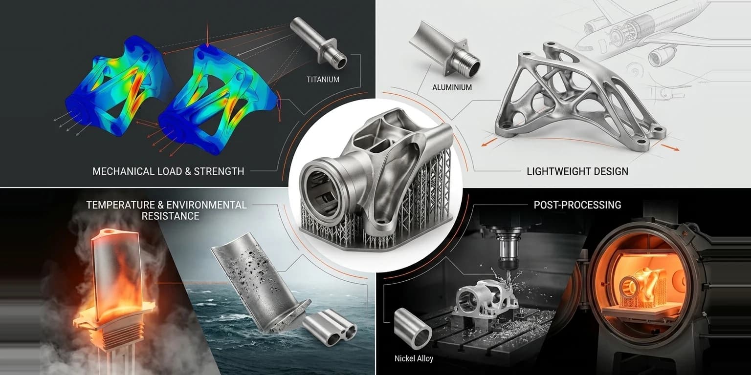
Metal AM lets designers place material where it contributes most to performance. Ribs, hollow regions, lattice structures and topology optimisation can remove unnecessary mass, but every redesign still has to meet loading, stiffness and fatigue requirements. Removing material without structural verification can create higher local stresses or reduce durability.
Real-world example: the Airbus titanium bracket
Airbus demonstrated the benefits of design for additive manufacturing through a titanium cabin bracket developed for the A350 XWB. The component was manufactured using a laser powder bed fusion-type process, replacing a conventionally machined aluminium design. As documented in a technical publication by researchers at the Karlsruhe Institute of Technology, the redesigned bracket achieved a weight reduction of more than 30%. It is a good illustration of topology optimisation and metal AM working together to create lightweight components that still meet structural requirements.
Core DfAM Design Rules for Laser Powder Bed Fusion
The guidelines below primarily concern metal L-PBF. They cover minimum features, overhangs, support placement, internal passages and geometric transitions. Wire-fed DED shares broad concerns such as heat management and finishing, but its bead-based constraints need separate consideration.
Wall thickness and minimum feature size
Wall thickness is among the first checks when deciding how to design parts for metal 3D printing. A wall that is too thin may fail to form consistently, distort during printing or be damaged during post-processing. The relevant limit depends on alloy and powder, laser parameters, wall height, length, orientation, nearby geometry, loads and finishing requirements. A short supported wall and a tall free-standing wall of identical thickness can behave very differently. Some L-PBF systems can produce sub-millimetre features, but that observation is not a universal design rule.
Practical example: a team developing a stainless-steel housing might print representative coupons with walls of 0.4, 0.6, 0.8 and 1.0 mm, then inspect their dimensions, surface condition and distortion. Those are experimental dimensions, not recommended minimums — the final choice has to come from qualified process data or validation.
Self-supporting angles and overhangs
An overhang extends beyond the solid material directly beneath it. In L-PBF, loose powder conducts heat and supports molten metal far less effectively than solid material, so downward-facing regions can develop rough surfaces, curling or dimensional errors. A common starting guideline is the 45-degree rule: surfaces shallower than roughly 45 degrees to the horizontal build plane may need supports or process development. It is not a universal limit, because material, feature span, machine settings and quality requirements all matter.
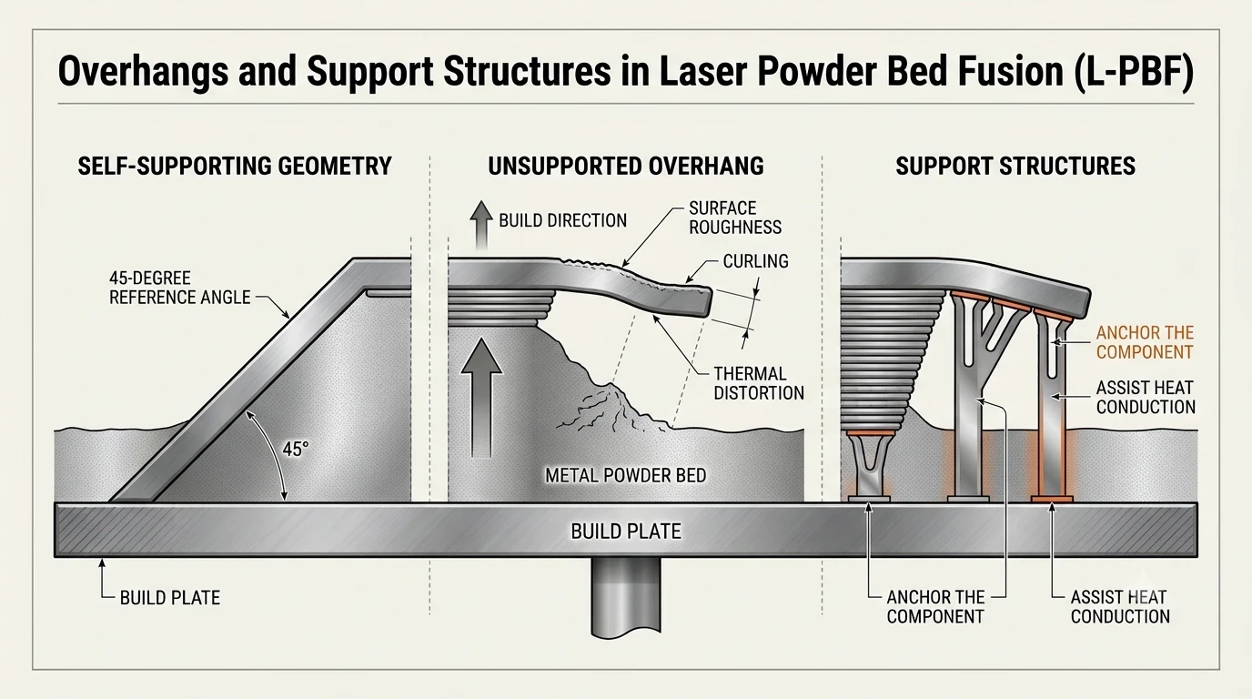
Practical example: a round horizontal cooling passage has a difficult downward-facing ceiling. A teardrop-shaped or otherwise self-supporting cross-section may reduce that problem, although the redesigned channel still has to meet its flow and pressure-drop requirements. Evaluate angle, unsupported span and functional surface quality together, not as isolated checklist items.
Reducing and Placing Support Structures
In L-PBF, supports anchor the part to the plate, conduct heat and reduce movement during building. They also consume material and require preparation and removal. A support on an accessible external face may be straightforward to remove, whereas a support inside a narrow passage may be impossible to reach. Part orientation and support design should therefore be reviewed together, including which tools will remove each structure afterwards.
Useful metal 3D printing design tips include putting supports on surfaces that will later be machined, reducing avoidable downward-facing areas, and avoiding inaccessible supported cavities. Do not remove supports indiscriminately: an aggressive reduction may increase distortion or make the build unstable. The right strategy balances build reliability against finishing effort. For a broader explanation of supports and powder-bed processing, see what is laser powder bed fusion.
Holes, Channels and Internal Passages
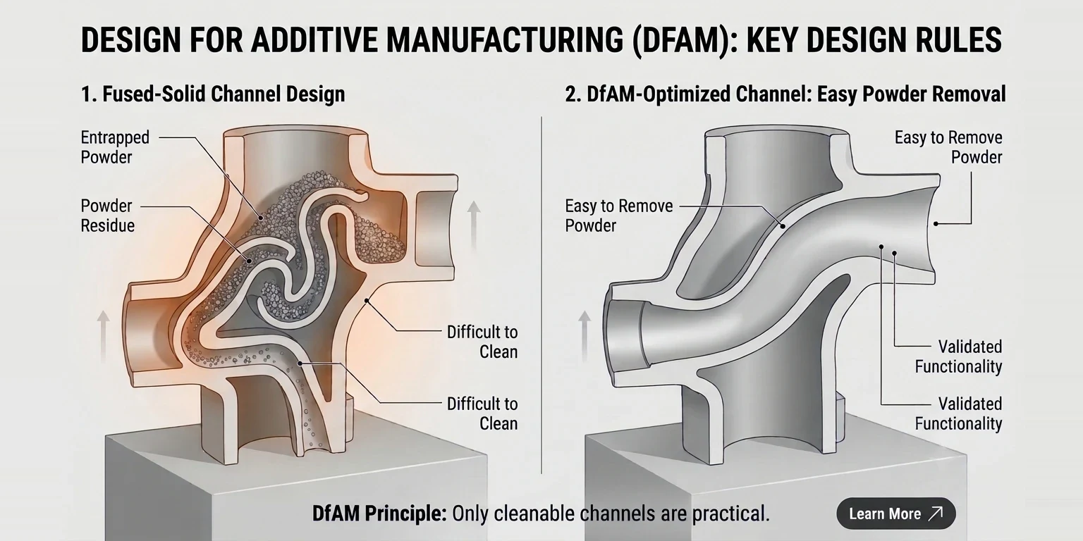
Internal channels are a large part of why L-PBF is attractive for fluid distribution and conformal cooling. However, unused powder remains in open spaces after the build, and a geometrically printable passage may still be impossible to clean. Narrow openings, sharp bends and sealed dead-end cavities can all obstruct powder removal. Assess passage size, escape openings, internal surface roughness, cleaning methods and inspection access from the outset.
Practical example: a mould insert with a cooling channel following its cavity surface may perform well in a thermal simulation. Before manufacturing, the engineer also has to determine how loose powder will leave the channel, and whether as-built roughness creates an unacceptable pressure drop. The design has to work as a physical, cleanable component, not only as an idealised fluid model.
Fillets, Radii and Stress Concentrations
Sharp corners and abrupt changes in cross-section concentrate mechanical stress. A bracket with a thin arm connected to a thicker mounting block, for example, may see increased local stress at that transition. A suitable fillet or gradual change in geometry can distribute loads more smoothly, although the necessary radius should come from analysis rather than an arbitrary rule of thumb.
Smooth transitions may also influence thermal behaviour during printing. Review highly loaded joints, abrupt thickness changes and tight internal corners early, then validate structural performance with suitable calculations, simulation or testing. A rounded feature is not automatically better if it creates unsupported geometry or interferes with required mating surfaces.
Designing to Control Distortion and Residual Stress
Metal AM involves repeated heating and cooling. Different regions of a growing component reach different temperatures, producing thermal expansion and contraction that can leave residual stresses after the build. Those internal stresses may contribute to deformation, warping or cracking. In L-PBF, rapid local melting and solidification can create steep thermal gradients; DED faces its own thermal challenges during repeated deposition passes.
The response combines design and process planning: avoid unnecessary abrupt changes in thickness, review long unsupported features, assess orientation and restraint, and plan heat treatment or machining where the application requires it. Process simulation can help estimate distortion on complex parts, but its predictions still need experimental confirmation before they are relied on for critical dimensions.
Part Orientation on the Build Plate
Orientation affects layer count, support requirements, thermal behaviour, surface finish, critical dimensions and how many components fit inside one build. A short build height can reduce recoating cycles, but it may also require more support material or leave a precision surface facing down. The shortest orientation is not automatically the most economical or the most reliable one.
How orientation affects layer count
Consider a component that could be built at 20 mm or 60 mm in height. At an illustrative 40 µm (0.04 mm) layer thickness, the two orientations need very different numbers of layers even though the part is identical.
| Build orientation | Build height | Calculated layers |
|---|---|---|
| Horizontal | 20 mm | 500 |
| Vertical | 60 mm | 1,500 |
The taller orientation requires three times as many layers and recoating cycles at the assumed layer thickness. It does not necessarily take three times the total manufacturing time, because laser scanning per layer, support volume and other parameters differ. A valid comparison needs an estimate of the full build and finishing route.
What engineers should prioritise
| Design priority | What to evaluate |
|---|---|
| Build time | Height, layers, scan length and preparation |
| Supports | Overhangs, volume and removal access |
| Surface quality | Position of critical faces and downward surfaces |
| Accuracy | Distortion and machining requirements |
| Mechanical properties | Direction-dependent performance and qualified parameters |
| Powder removal | Channels, trapped cavities and escape paths |
| Build efficiency | Packing multiple parts into the available volume |
For a bracket with precision mating surfaces, an orientation that protects those surfaces may be worth more than one that minimises layer count. For research coupons, a consistent orientation may be needed to produce comparable mechanical-test data.
Lightweighting: Lattices and Topology Optimisation
Lattice structures and topology optimisation are two ways to distribute material more deliberately. Neither guarantees an improvement simply because the geometry looks complex. The right approach depends on loads, stiffness, thermal or flow objectives, manufacturability and inspection needs.
Lattice structures and TPMS
A lattice uses an interconnected network of repeating features rather than a solid volume. Depending on cell shape, it may reduce mass, control stiffness, absorb energy or increase surface area for heat transfer. Triply Periodic Minimal Surface (TPMS) geometries, including gyroid-like forms, are of interest in heat exchangers because they create continuous surfaces within a compact envelope.
These structures bring trade-offs of their own. Small features may be difficult to print, enclosed cells may trap powder, and rough internal surfaces increase both heat transfer and fluid pressure drop.
Topology optimisation
Topology optimisation uses computational methods to identify where material is most useful within a defined design space. An engineer supplies loading conditions, constraints and performance targets, and the software explores possible distributions of material. The result can be an organic-looking bracket that is difficult to machine but potentially well suited to additive manufacturing.
The optimised shape still needs a DfAM review. Check overhangs, minimum feature sizes, build orientation, supports, fatigue performance and machining access before approving it. Topology optimisation identifies a candidate geometry; it does not certify that the geometry can be printed or that the finished part will meet every specification.
How Does DfAM Change for Wire-Fed DED?
Unlike L-PBF, wire-fed DED builds geometry from deposited tracks and layers rather than scanning areas within a powder bed. The main design questions concern deposition access, bead dimensions, heat input, substrate behaviour and finishing allowances — which matters particularly for engineers working across more than one process.
Deposition path and head access
A DED head and its wire-delivery arrangement need enough clearance to reach the planned deposition region. Deep recesses, narrow gaps or obstructions can prevent the system from following the required path even when the CAD model is geometrically valid. Available motion axes, toolpath planning and potential head collisions should be checked before committing to the part design. A tall wall surrounding a small recessed repair location might block direct head access, and the team may need a different orientation, deposition sequence, preparation method or process. In DED, access is a primary design constraint, not something left to the machine operator.
Bead geometry and feature resolution
Wire-fed DED produces overlapping beads whose width, height and consistency determine the resolution of the resulting geometry. Very narrow walls, fine lattices or sharp internal corners can fall below the achievable feature size of a given process. Rather than forcing unsupported detail, engineers often deposit a larger near-net shape and machine the critical regions to specification. A mounting face, for example, can be deposited with extra material and later CNC machined to its specified flatness. The allowance depends on bead size, heat-induced distortion and the finishing method, and should come from actual process evidence rather than one universal number.
Heat accumulation and substrate behaviour
Each deposition pass adds heat to the growing part and the substrate beneath it. Temperature can accumulate unevenly, affecting bead geometry, residual stresses and dimensions. The substrate’s alloy, thickness, geometry and restraint all influence how heat spreads, so design and path planning have to be considered together. A series of repeated tracks in one small region may create local heat build-up, and an alternative travel sequence, cooling interval or validated control strategy could be necessary.
Repair and cladding applications
DED can add material to an accessible part of an existing metal component. Repair typically replaces lost material, while cladding adds a layer for a specified surface function. On a worn shaft, where the substrate and service conditions are suitable, material can be deposited onto the worn area and then machined back to the required dimensions. Success depends on more than the deposition: access, base-metal condition, material compatibility, thermal effects, machining allowance and inspection requirements all matter, and not every damaged component can be repaired economically or safely. For the process itself, see what is directed energy deposition.
Practical DfAM Example: Redesigning a Metal Mounting Bracket
Consider a machined bracket with a thick body, two mounting holes and an extended arm. It has to carry a defined load and maintain alignment between its mounting surfaces. An engineer wants to prototype it using L-PBF, and instead of copying the CAD file unchanged, the team reviews both its functional requirements and its manufacturing constraints.
Step 1: Define what cannot change
The mounting-hole locations, load paths and contact surfaces are functional constraints. Removing material or modifying the shape is acceptable only if those requirements stay satisfied. The design review identifies which areas are essential and which can be revised for additive manufacture.
Step 2: Identify manufacturing risks
The existing bracket has a broad horizontal overhang that may require extensive support. It also includes a narrow pocket that could be difficult to clean, and two holes whose tolerances may require machining. Those risks inform the next design iteration rather than being discovered after printing.
Step 3: Redesign for the process
Where structural analysis permits, some solid areas can be replaced by ribs or smoother transitions. The engineer can rotate the part to reduce difficult overhangs and move supports to accessible, non-critical faces. Every change is evaluated against load, stiffness and manufacturability rather than judged on weight reduction alone.
Step 4: Plan finishing and inspection
The mounting holes can be produced with a suitable machining allowance and later drilled or reamed. The team defines workholding datums, support removal, cleaning and the dimensions to inspect, so the manufacturing plan covers the finished bracket rather than just the printed blank.
Step 5: Print, measure and refine
The revised bracket is printed, finished and inspected. Measured dimensions and any required functional tests determine whether it meets the specification. This is an illustrative workflow rather than a claimed production result: the broader lesson is that DfAM combines geometry, manufacturing and validation in one decision process.
Designing for Post-Processing and Inspection
A printed metal part may still need cleaning, support removal, heat treatment, machining, surface finishing or inspection. Which operations apply depends on material, geometry and service requirements, but they should never be an afterthought. Designing only for the build can leave critical surfaces inaccessible or make the final component unnecessarily expensive.
- Machining allowances and critical surfaces — precision mounting holes, bearing seats, sealing faces and threaded features may need machining after printing. A machining allowance is intentional extra material that can be removed to achieve final dimensions or finish; the amount depends on process capability, distortion risk, geometry and workholding.
- Access for finishing — finishing equipment has to reach the surfaces that need it. This matters most for deep recesses, channels and surfaces behind other features. Consider access for cutting tools, support removal and cleaning during CAD development, rather than discovering after printing that a required operation is impossible.
- Inspection requirements — external dimensions alone do not establish part quality. Depending on the application, inspection may include dimensional measurement, roughness, mechanical tests or non-destructive methods such as computed tomography. A teaching demonstrator has different requirements from a safety-critical component.
How Can Good Design Reduce Metal 3D Printing Cost?
Good design reduces metal 3D printing cost by improving the complete manufacturing route, not just the volume of printed material. Three common opportunities are reducing unnecessary supports, selecting an efficient orientation and making finishing easier. Each can lower labour or machine requirements, and each must also preserve build reliability and functional performance.
Changing an overhang may reduce support removal; lowering build height may reduce recoating cycles; placing supports away from a precision face may simplify machining. These effects should be costed together, because one improvement can increase a different expense. The objective is the total cost of producing a finished component that meets its specification.
| Cost driver | DfAM opportunity |
|---|---|
| Build preparation | Simplify geometry and support planning |
| Build time | Evaluate orientation, height and scanning |
| Support material | Reduce avoidable supported areas |
| Failed builds | Validate difficult features before production |
| Finishing labour | Improve support and machining access |
| Inspection | Provide measurable and accessible critical features |
| Assembly | Consolidate components where justified |
Common DfAM Mistakes to Avoid
The most costly mistakes are usually the ones discovered only after a complete build. The table below highlights the errors worth reviewing early, including cases where an otherwise strong conventional design is simply unsuitable for additive manufacture.
| Common mistake | Why it matters | Better approach |
|---|---|---|
| Copying a machined design directly | Original geometry may be unsuitable for layer-wise processing | Review the design for the selected AM process |
| Using unvalidated thin walls | Features may deform or fail to form | Test representative coupons and use qualified limits |
| Ignoring overhangs | Unsupported faces may develop defects | Review orientation and self-supporting alternatives |
| Placing inaccessible supports | Supports may be impossible to remove | Plan post-build access at the CAD stage |
| Creating sealed cavities | Powder may remain trapped | Provide suitable evacuation routes |
| Ignoring residual stress | The part may distort or crack | Assess thermal behaviour, supports and restraint |
| Using untested lattices | Thin cells and passages may not print consistently | Validate representative structures |
| Expecting final tolerances as-built | Critical faces may need machining | Plan allowances and inspection |
| Assuming lighter means stronger | Material removal can harm stiffness or fatigue life | Validate revised load paths |
| Selecting DED for fine detail | Bead size may prevent the geometry | Choose another process or machine features afterwards |
| Choosing the process too late | Major redesign may be unavoidable | Compare technologies before freezing the geometry |
DfAM Checklist Before You Print
Use this list during design review, not as a replacement for material qualification or industry-specific acceptance requirements. Critical applications may need additional engineering review, testing and compliance work.
Geometry and process
- The selected process suits the part’s size, alloy and geometry.
- Minimum wall thickness and key feature sizes are validated.
- Overhangs, spans, fillets and transitions have been assessed.
- The component fits the usable machine build volume.
Build preparation
- Orientation has been checked for time, quality and support volume.
- Supports can be removed without damaging critical surfaces.
- Internal passages have cleaning and inspection access.
- Distortion and thermal risks have been considered.
- DED head access, bead dimensions and paths are checked where relevant.
Post-processing and quality
- Machining allowances and workholding requirements are defined.
- Cleaning, powder removal and finishing methods are feasible.
- Critical dimensions and acceptance criteria are documented.
- Suitable inspection methods are planned.
Cost and production
- Build, material, support and setup costs are included.
- Heat treatment, machining and inspection costs are included.
- The process offers a defensible benefit over the alternatives.
- Repeatability or qualification requirements are understood.
For formal process-specific design guidance, engineers may consult ISO/ASTM 52911-1:2019 for laser-based powder bed fusion of metals and ASTM F3413-19e1 for directed energy deposition. These standards complement rather than replace validated machine, alloy and process data.
Exploring DfAM With Lasefinity’s Metal 3D Printing Systems
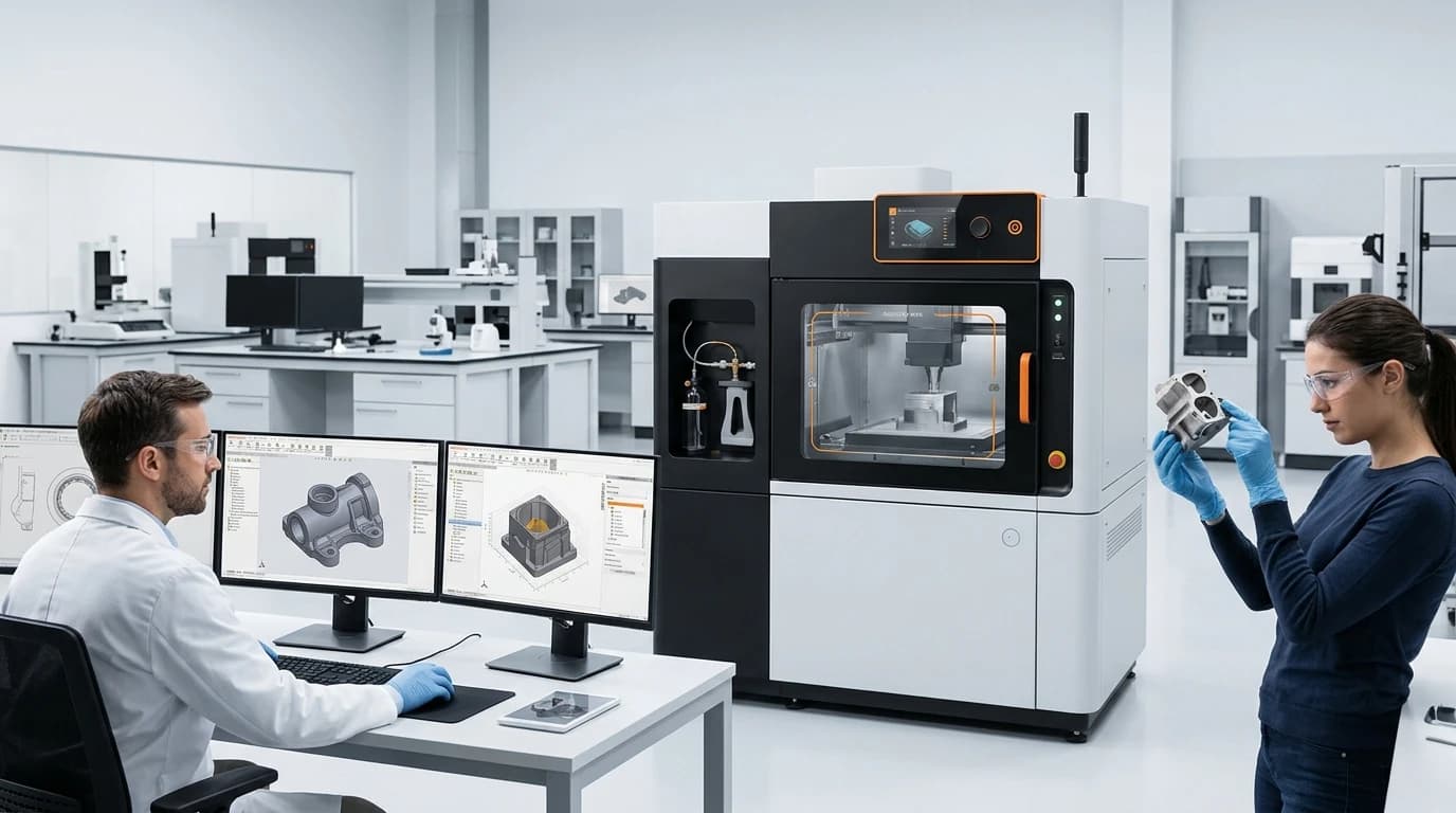
Lasefinity develops metal additive manufacturing systems for engineering, research, education and prototyping. FusionX and WireX illustrate why DfAM requirements have to be evaluated against the selected technology rather than treated as universal metal-printing rules.
FusionX: exploring L-PBF design requirements
FusionX is our L-PBF system, with a 500 W fibre laser, an adjustable 50–200 µm beam size and a 100 × 100 × 80 mm build volume. It provides a platform for research into orientation, supports, thin walls, feature geometry, surface condition and process parameters. These published specifications describe the equipment; they do not guarantee a particular minimum printable thickness or tolerance.
Explore the FusionX L-PBF metal 3D printer
WireX: studying design for wire-fed DED
WireX is a compact wire-fed DED system with a 150 × 150 × 150 mm build volume, up to 3,000 W combined fibre-laser power and compatibility with 0.4–0.8 mm wire diameters. It supports studies of deposition paths, bead formation, thermal behaviour and near-net-shape structures, with integrated melt-pool monitoring. Feature limits and repair suitability still depend on validated materials, parameters and component requirements.
Explore the WireX wire-fed DED printer
Which system fits the design?
A project involving fine detail, complex lattices or enclosed passages may favour L-PBF, provided supports and powder removal are manageable. An accessible repair or a controlled material-deposition study may favour wire-fed DED. Neither process is universally better: the choice should follow the component’s geometry, material, performance targets, production volume and finishing needs.
Final Thoughts
Design for additive manufacturing is about making sound engineering decisions before printing begins. A CAD model may be geometrically valid yet difficult to manufacture, finish or inspect. Wall thickness, overhangs, supports, orientation, residual stress and cleaning all influence whether a printed metal part can meet its real-world requirements.
For L-PBF, attention to support strategy, powder removal and surface quality makes complex geometry more practical. For wire-fed DED, deposition access, bead geometry, substrate behaviour and machining allowances become equally important. The most reliable approach is to start with the part’s function, choose an appropriate process, and validate the features that carry the greatest manufacturing risk.
Planning to manufacture a metal component using additive manufacturing? Get in touch with the Lasefinity team to discuss the geometry, material, tolerances and intended application, and we will help assess whether L-PBF, wire-fed DED or another manufacturing route is suitable.